


Details
Beam Bridge
Executive plan
Location
Portogruaro (VE) – S.S. N.14 “Della Venezia Giulia” – Portogruaro Bypass
Principal
ANAS S.p.A
Contracting company
- TECNIS S.p.A.
- MBM S.p.A.
- RICCIARDELLO Costruzioni
Team
Matildi+Partners srl
Activities
Executive plan (scaffolding)
Time Period
2005 – 2009
Extent and spans
575 m | 31+57+57+57+57+57+57+57+57+57+31
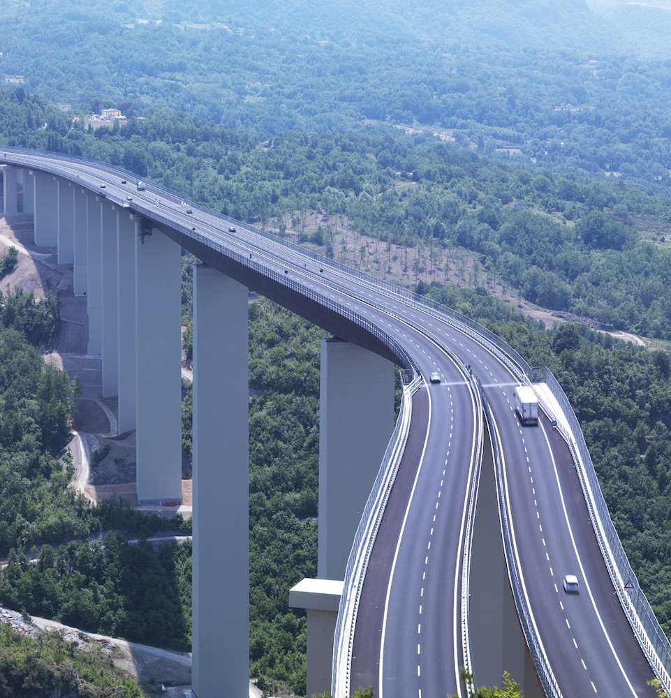
Structural Layout
Structural Layout
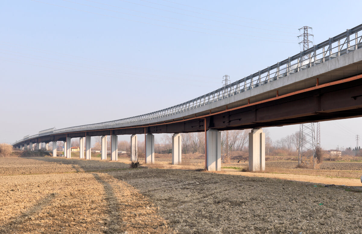
Detailed executive plan of the metal deck of the Lemène viaduct, located on S.S. No. 14 and included in the “Portogruaro Bypass” – IV Lot I Segment.
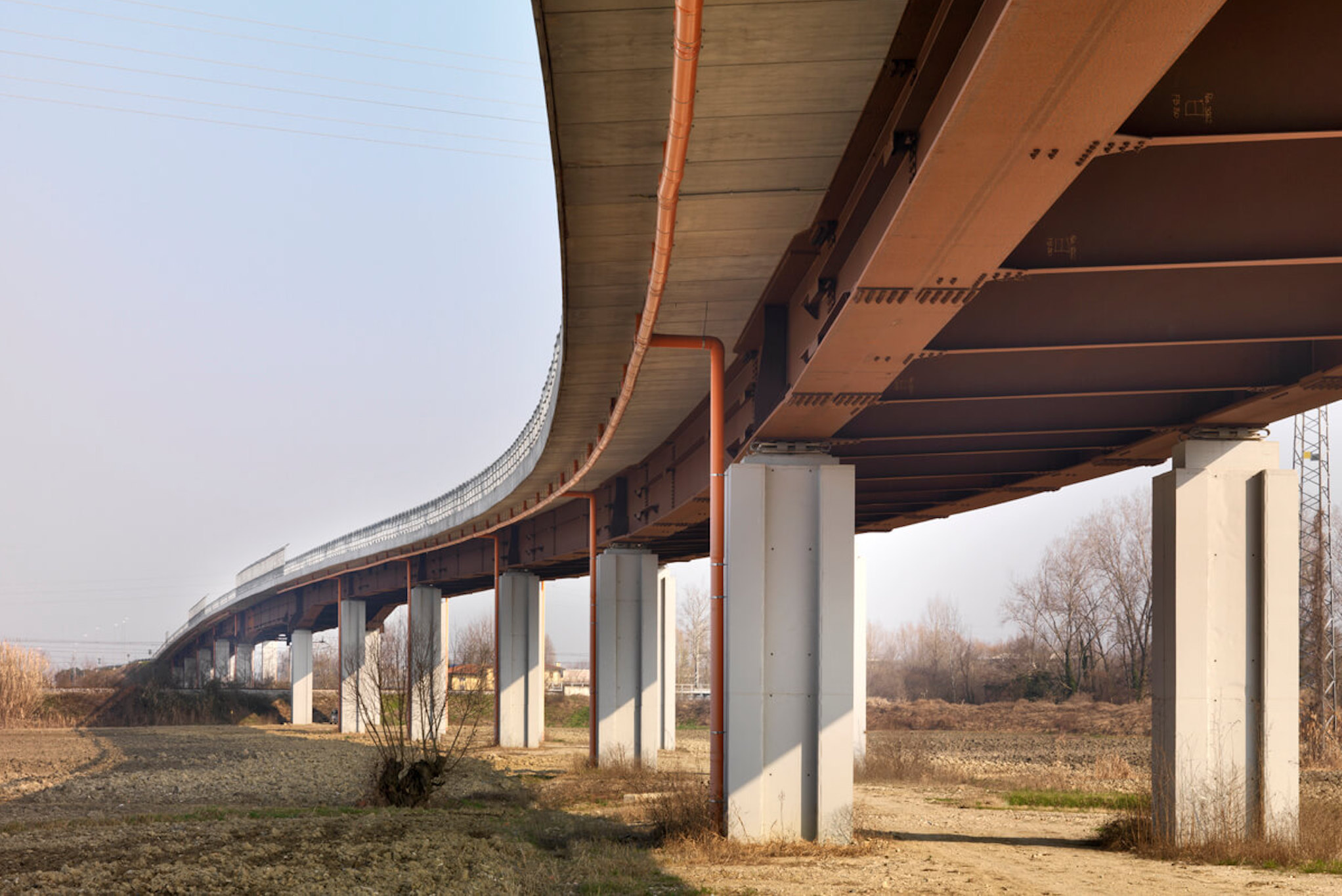
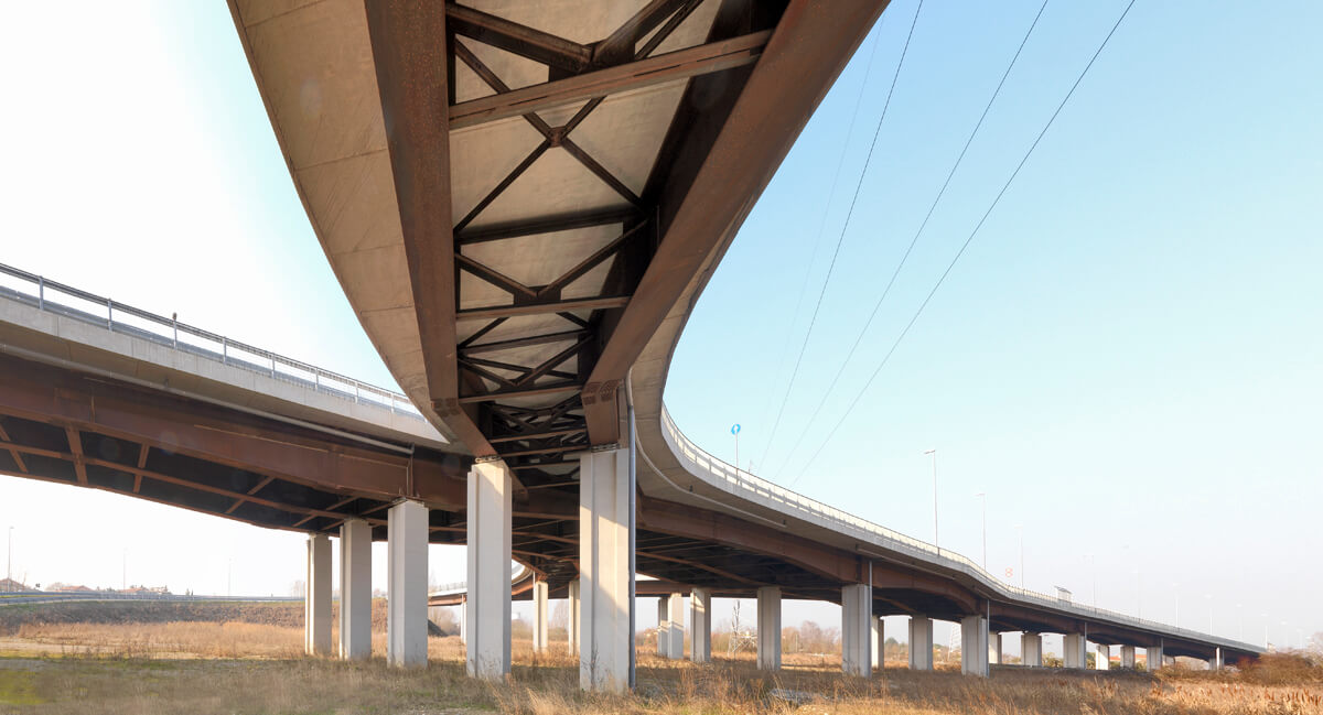
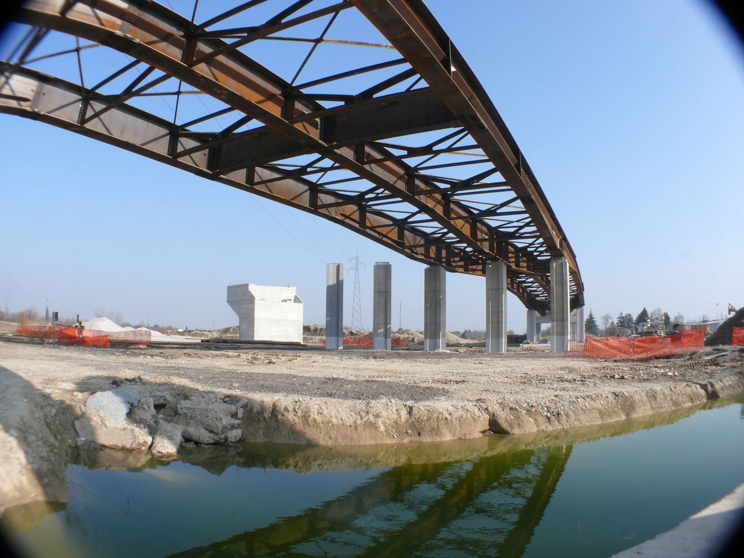
The new deck is a continuous truss in a composite steel-concrete system with eleven spans of 31+57+57+57+57+57+57+57+31 m.
Three junction branches with a total length of 190 m and typical spans of 40 m, 30 m and 20 m are connected to the main viaduct.
Slab

Slab
The concrete slab accommodates the road platform and two pavements, varying in width from 13 m to 20.50 m along the main axis of the viaduct, while at the junctions it varies from 9 m to 10.50 m.
For the section with a constant width of 13 m, a “caisson” type solution was adopted, while for the remaining section of the viaduct and the junctions, a “lattice” type solution was adopted.
The slab, with a total thickness of 30 cm, is cast in situ on self-supporting concrete predalles.
For the main viaduct, in the “caisson” section the slab is frame worked on 2 beams spaced 6.50 m apart, while in the “lattice” section the slab is frame worked on 3 beams with spacing varying from a minimum of 3.25 m to a maximum of 7.00. For the junctions, the slab is frame worked on 2 or 3 beams spaced 4.50 m and 4.00 m apart, respectively.
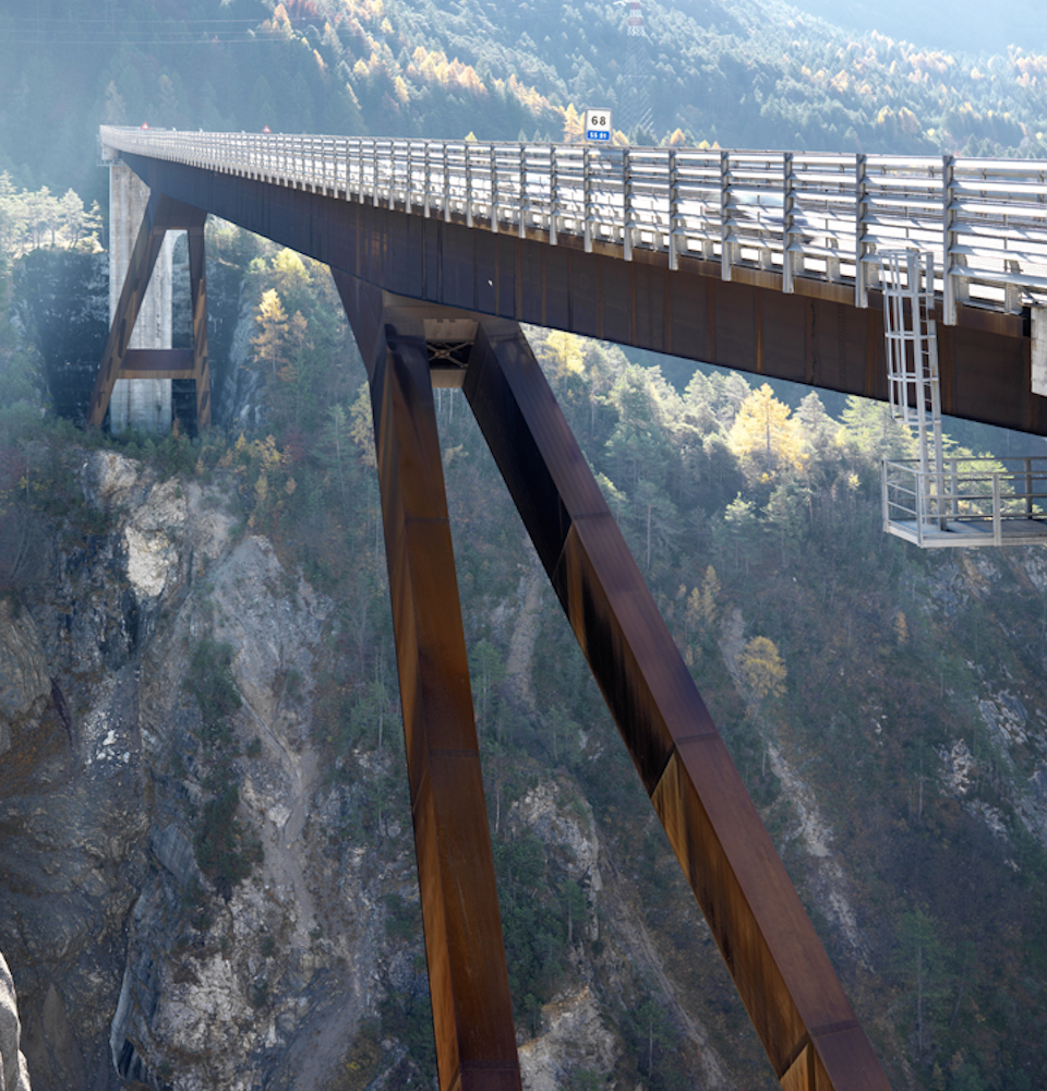
Deck and Assembly

Deck and Assembly
The beams vary in height from a minimum of 1.80 m in the abutment and span to a maximum of 2.60 m at the pier for both the “caisson” and “lattice” sections.
In the “caisson” section, they are connected by lattice-type diaphragms placed at constant centre distances of 6.0 m and by a lower bracing in the form of a St. Andrew’s cross which is required to ensure torsion-rigid caisson behaviour, while in the “lattice” section, the diaphragms are placed at centre distances of 4.0 m.
Assembly of the deck is carried out by lifting the individual beams from below with the aid of a crane truck, after assembly of the segments on the ground and subsequent forward advancement.


