


Details
Arch Bridge
Executive plan
Location
SS 79 bis “Ternana” overpassing the Valnerina
Principal
ANAS S.p.A
Contracting company
Consorzio Stabile UNITER (civil works) Maeg s.p.a.(metal fabrication)
Team
Plan executed by Matildi+Partners srl
A.T.P.: S.T.E.srl – SAB engineering – AGT ingegneria – AI engineering – Golder – AI Studio – Progter .
Activities
Executive design plan (deck and foundations)
Time Period
2006 – 2010 (inaugurated in 2013)
Extent and spans
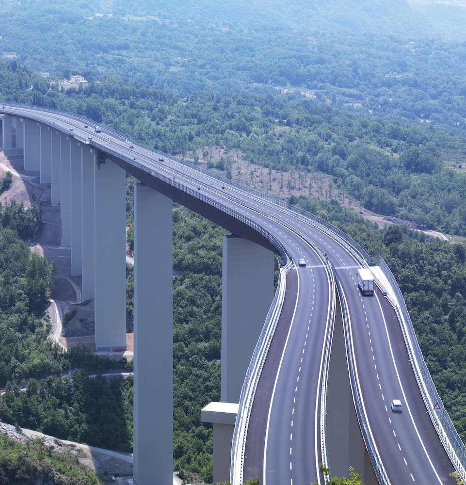
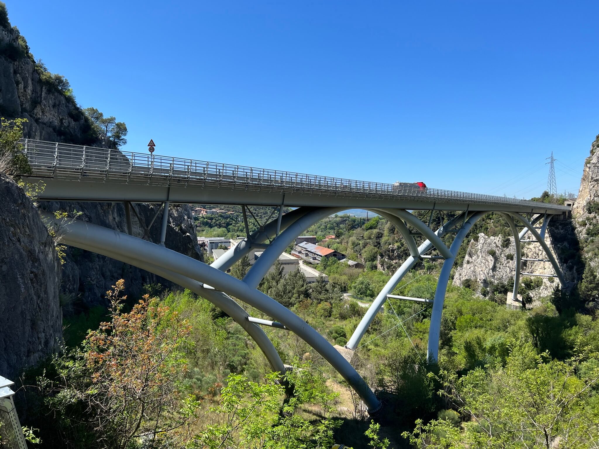
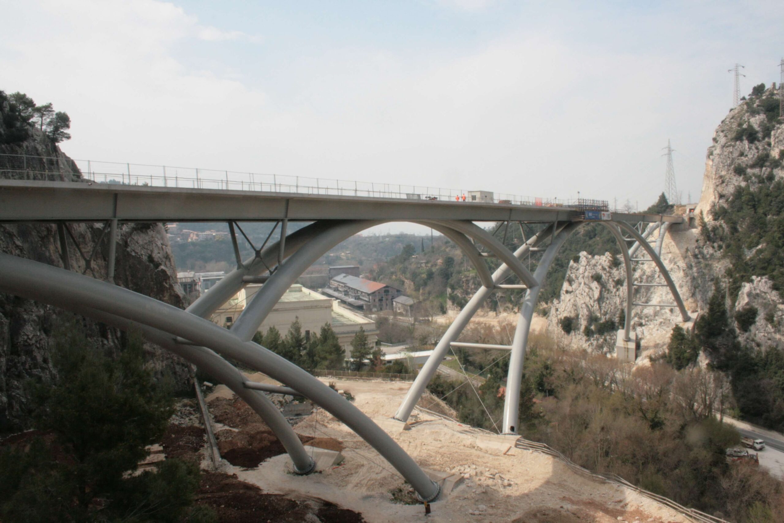
Total length 300 m – height 70m – Main arch span 170m

Structural Layout

Structural Layout
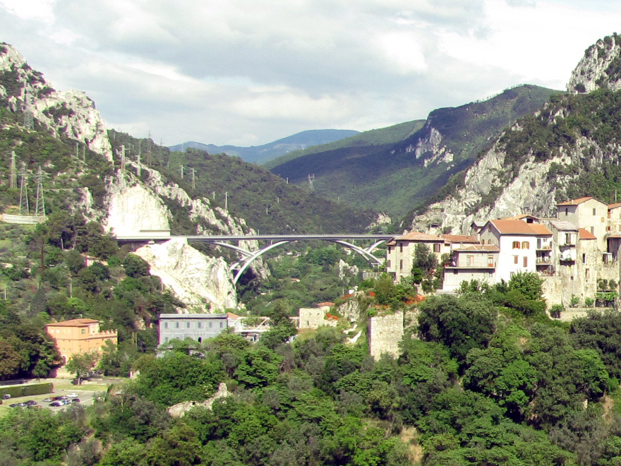
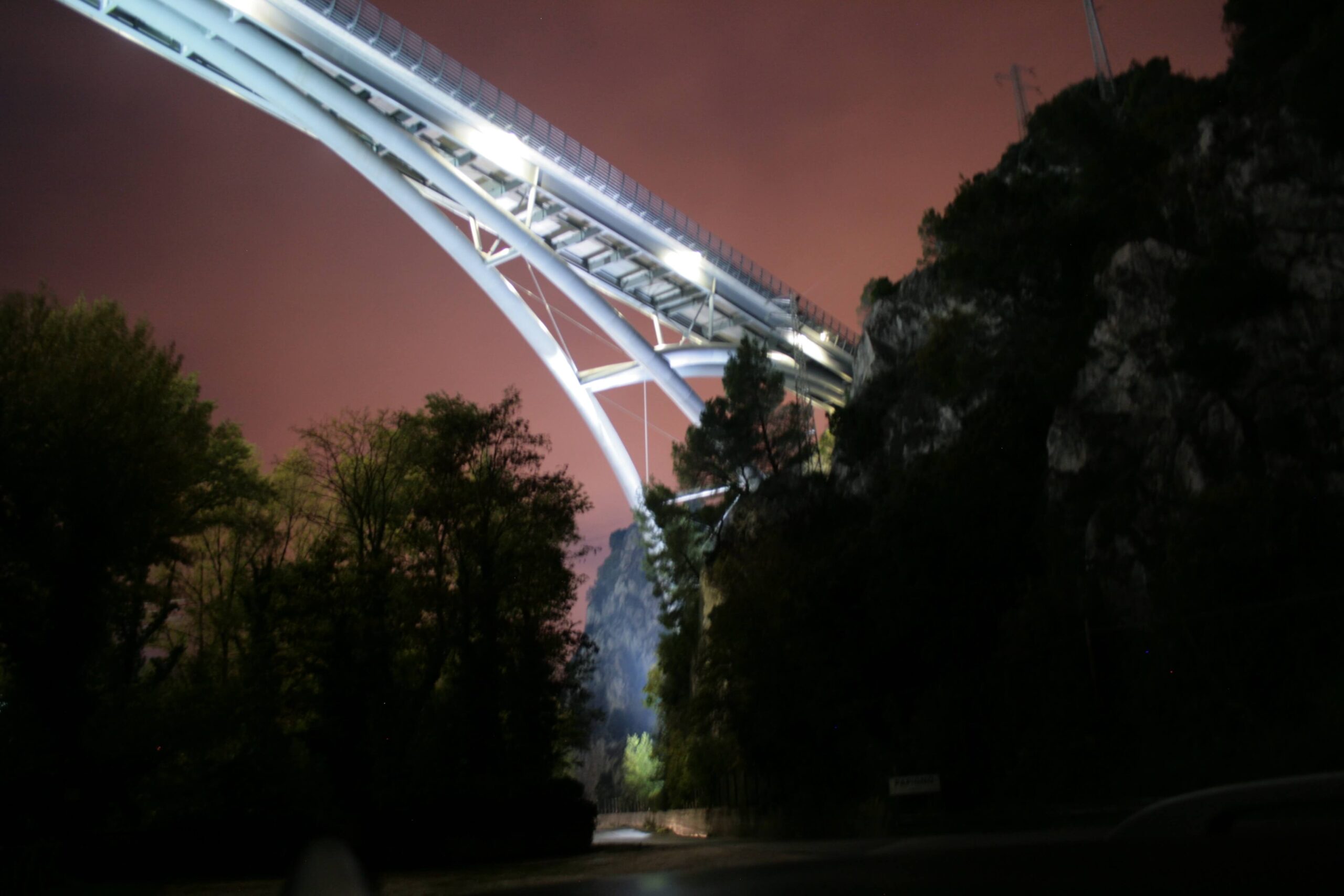
Plan for new bridge over the river Nera as part of the construction of the Terni (locality S.Carlo) – regional boundary (locality Piè di Moggio) section of the SS79bis on the Civitavecchia – Orte – Terni – Rieti route
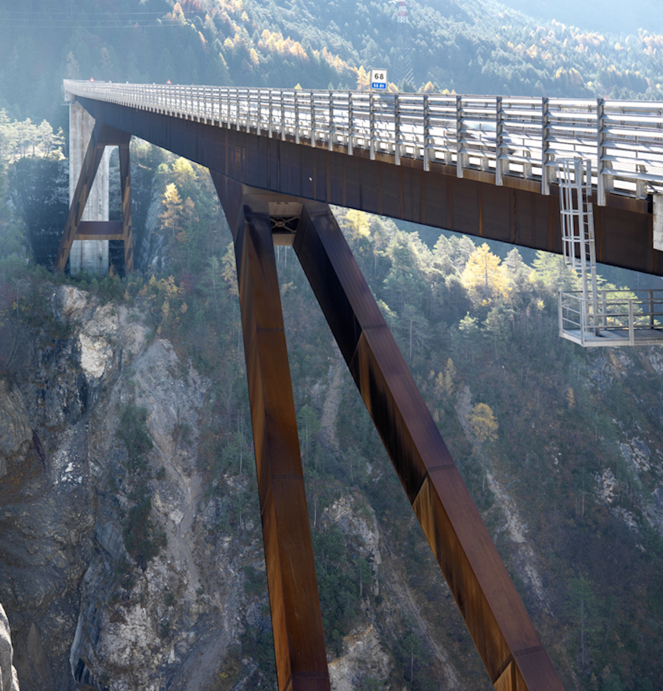
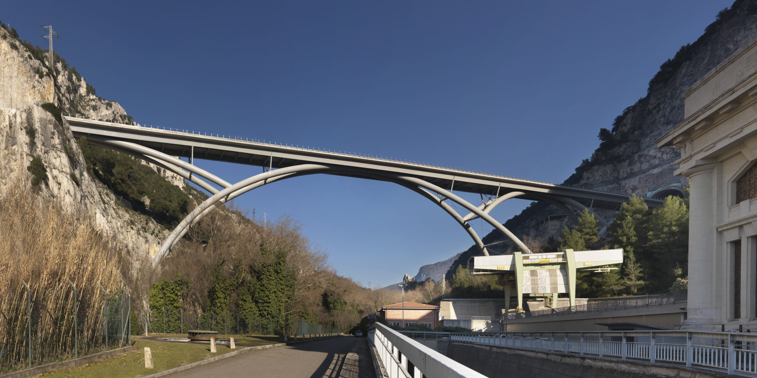
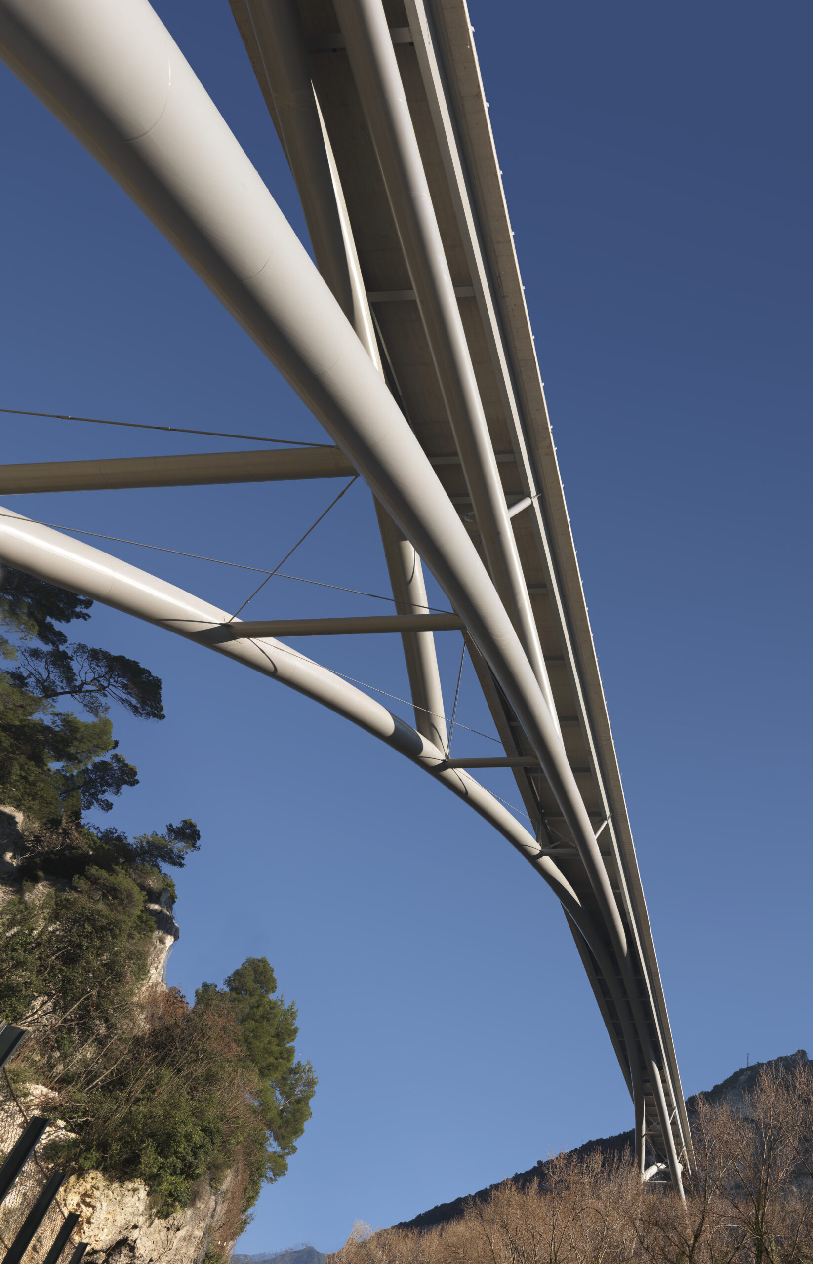
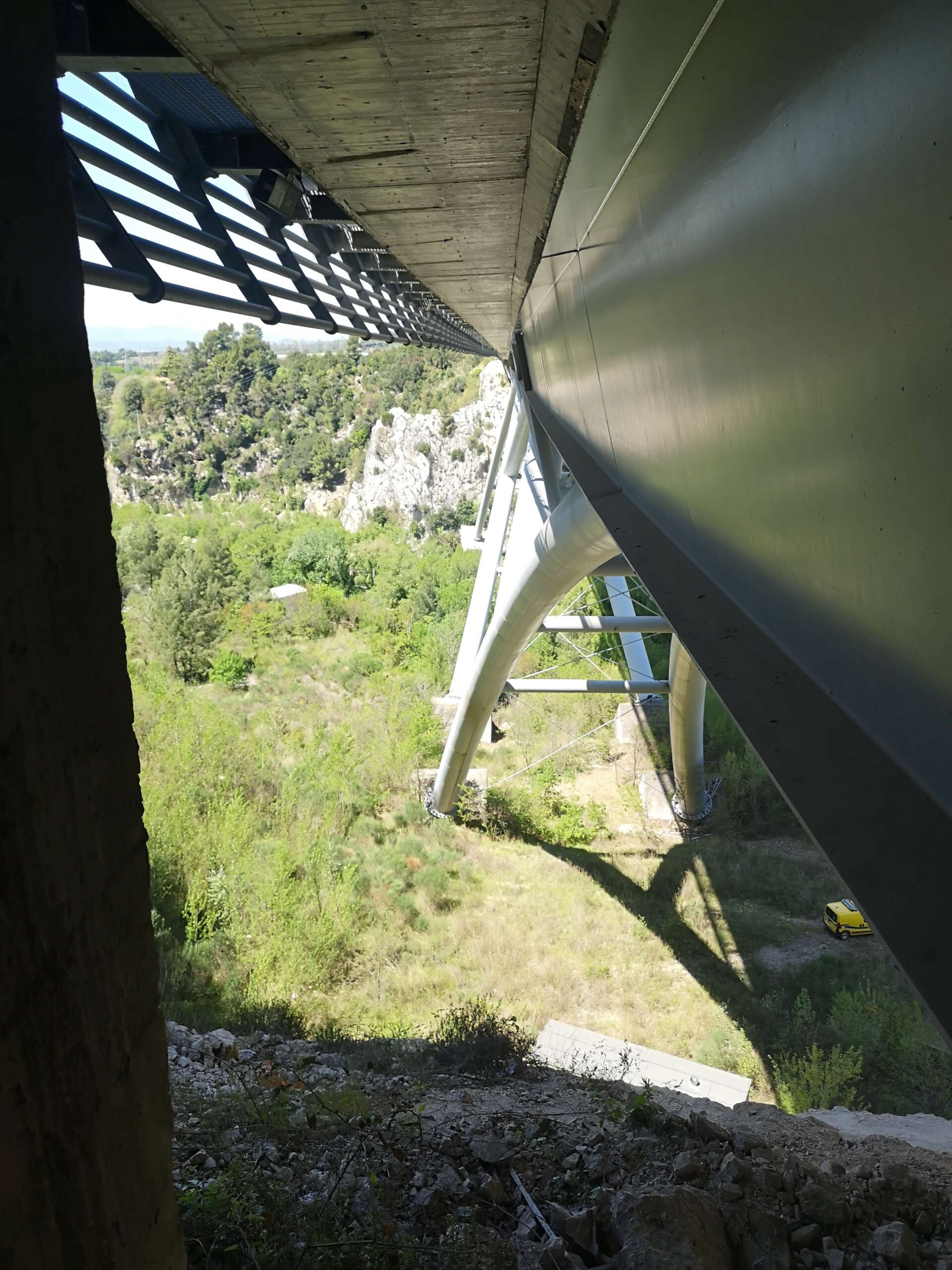
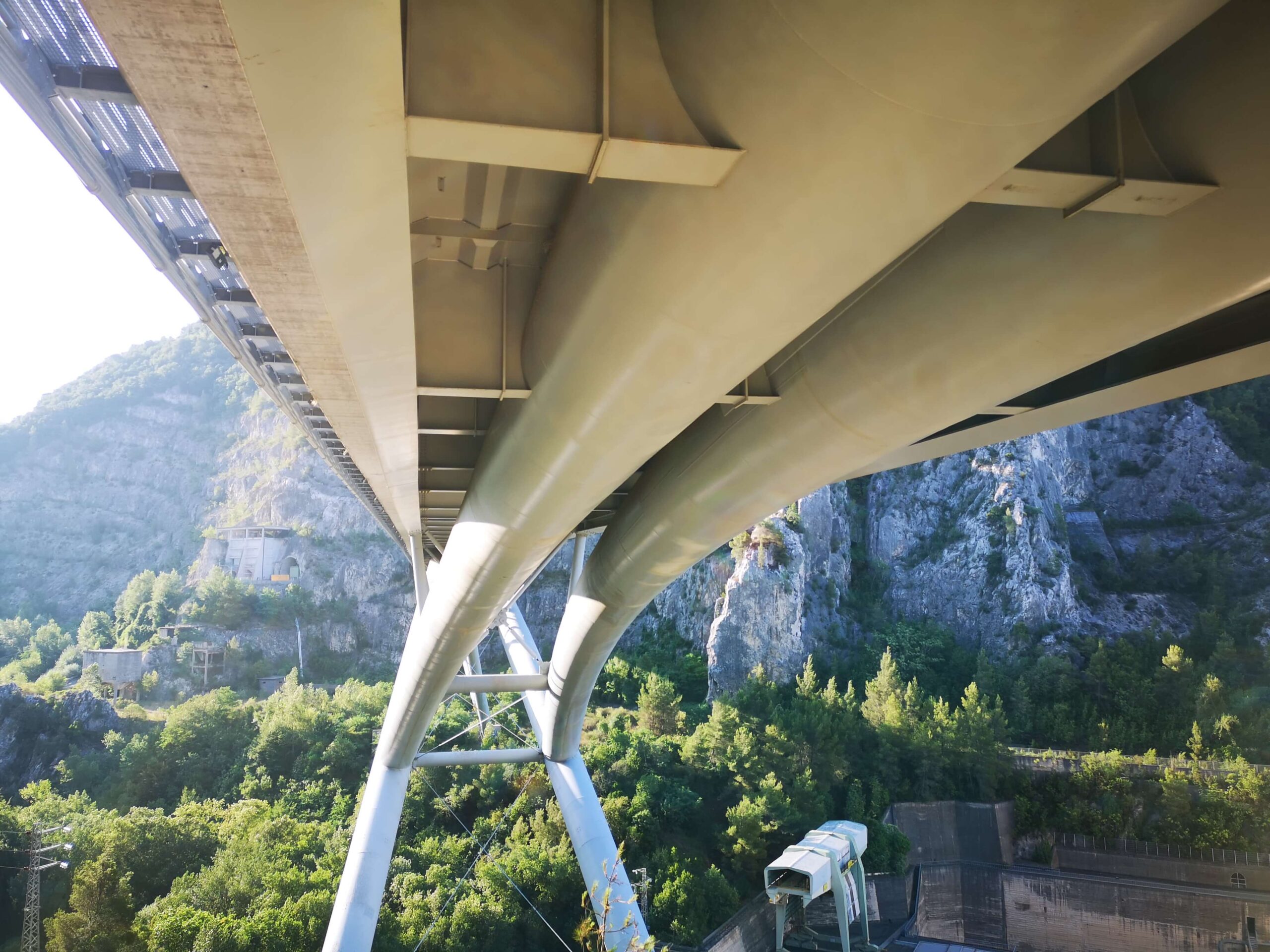
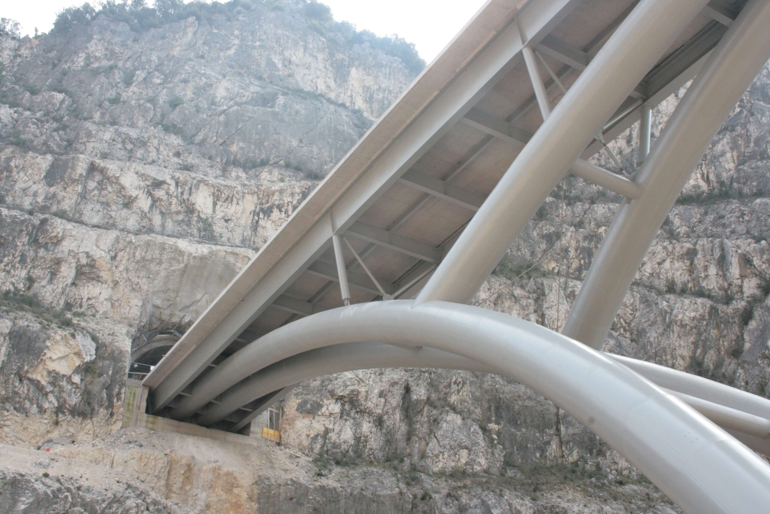
The new bridge features an upper deck design supported by two frames composed of Ø2200 tubing with two metal arch frames, the main one consisting of a metal arch with a main span of 170m and a semi-arch spanning 76m that rests on the rock face to the south at the tunnel entrance; the secondary arch rests on the main arches and consists of an arch and a semi-arch that rests on the slope to the north.
The secondary frame working is integrated with intermediate supports made of metal columns to ensure widespread support of the deck in a composite system for a total length of 300m.
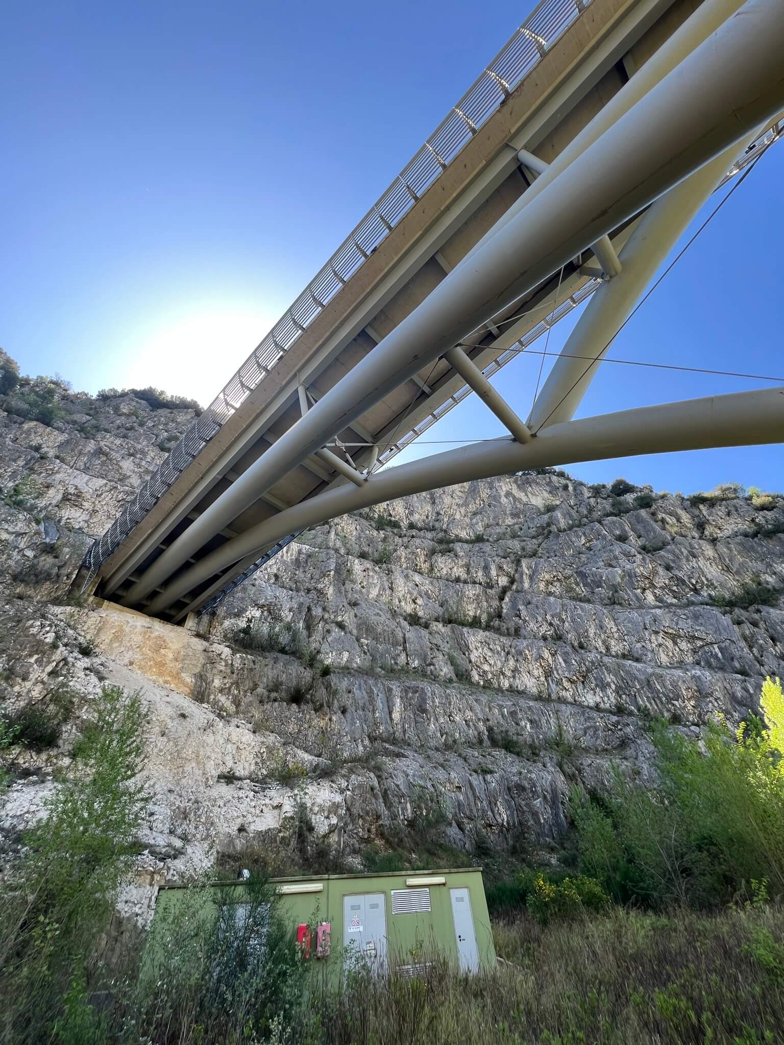
Slab and Arches

Slab and Arches
The concrete slab is 24 cm thick and was cast on site on sliding formwork, a solution that was considered to be easier for the construction of the segments head on to the 70 m arch at the bottom of the valley and to facilitate the support on the inclined beams of the deck and the section-breaker beam with suitable profiling.
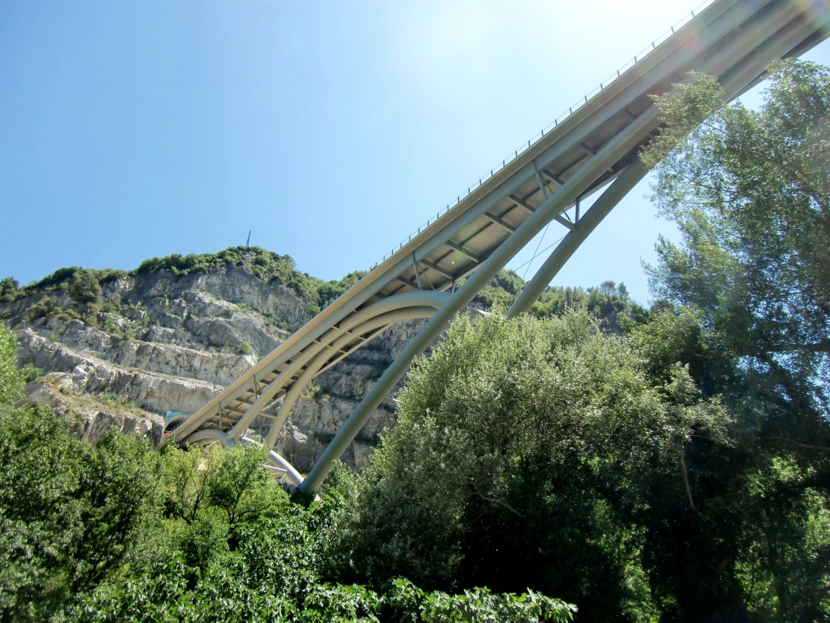
The tubing that constitutes the arches has a diameter of 2200mm, the radii of curvature vary from 76m to 125m for the main arch to approximately 60 for the secondary frame working arch.
Head on, the tubing section is tapered so that it fits into the same footprint as the deck beams.
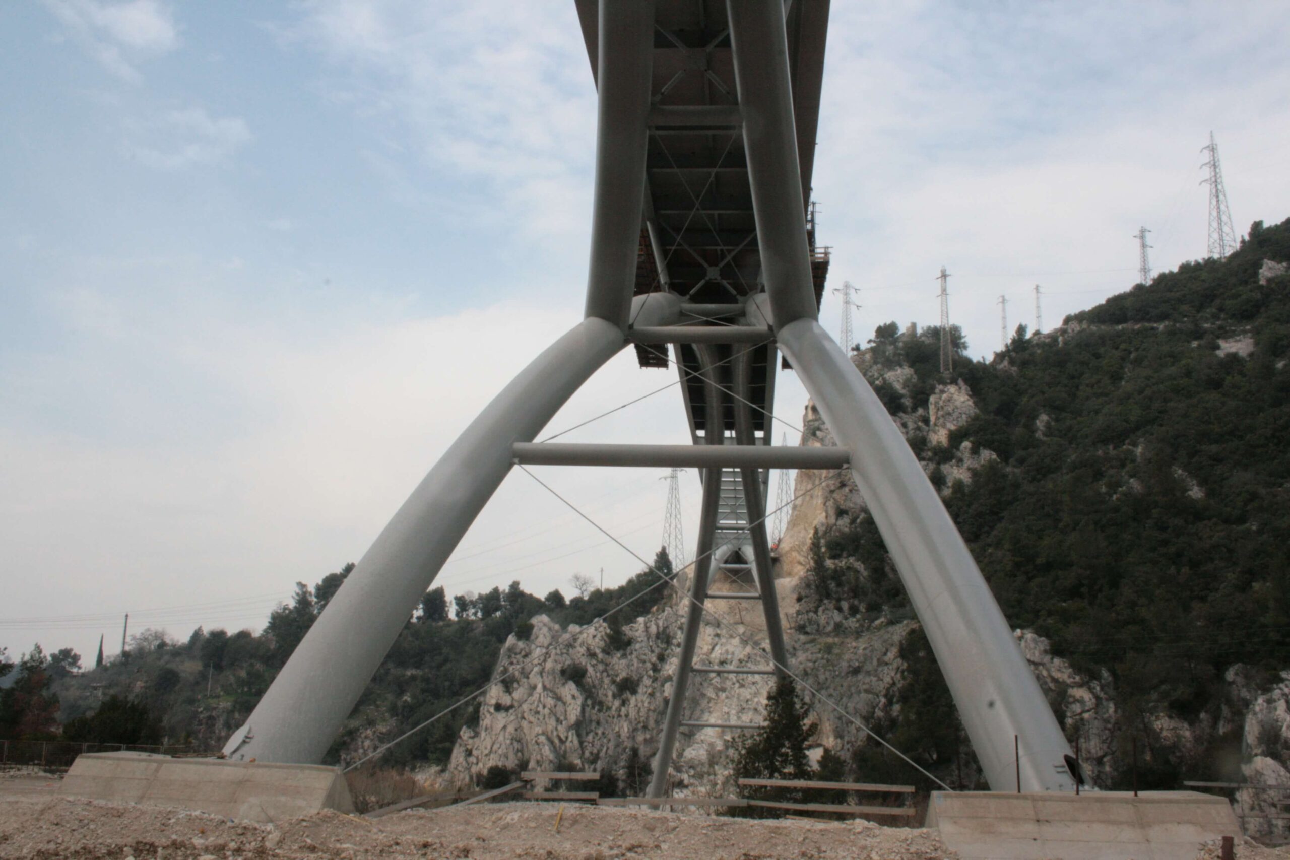
The arches are arranged in planes inclined at 14° to the horizontal and converge with a spacing head on of 2.7m and approximately 20m at the base.
Deck Beams and Foundation System

Deck Beams and Foundation System
The deck beams consist of double-T sections, which work together with the slab, have a constant height of 2m and are inclined outwards by 12° from the vertical so as to be coplanar with the intermediate support uprights.
The central foundation of the arches of the main frame working has a plan view dimension of 25m x 28m with an average thickness of 6m. Its geometry was designed so as to position its centre of gravity inside the compact rock zone and to avoid bearing on the adjacent debris layer having poor geotechnical properties. The foundations to the north were limited in size (8m x 8m in plan view) to facilitate their arrangement on the steep north rock slope.
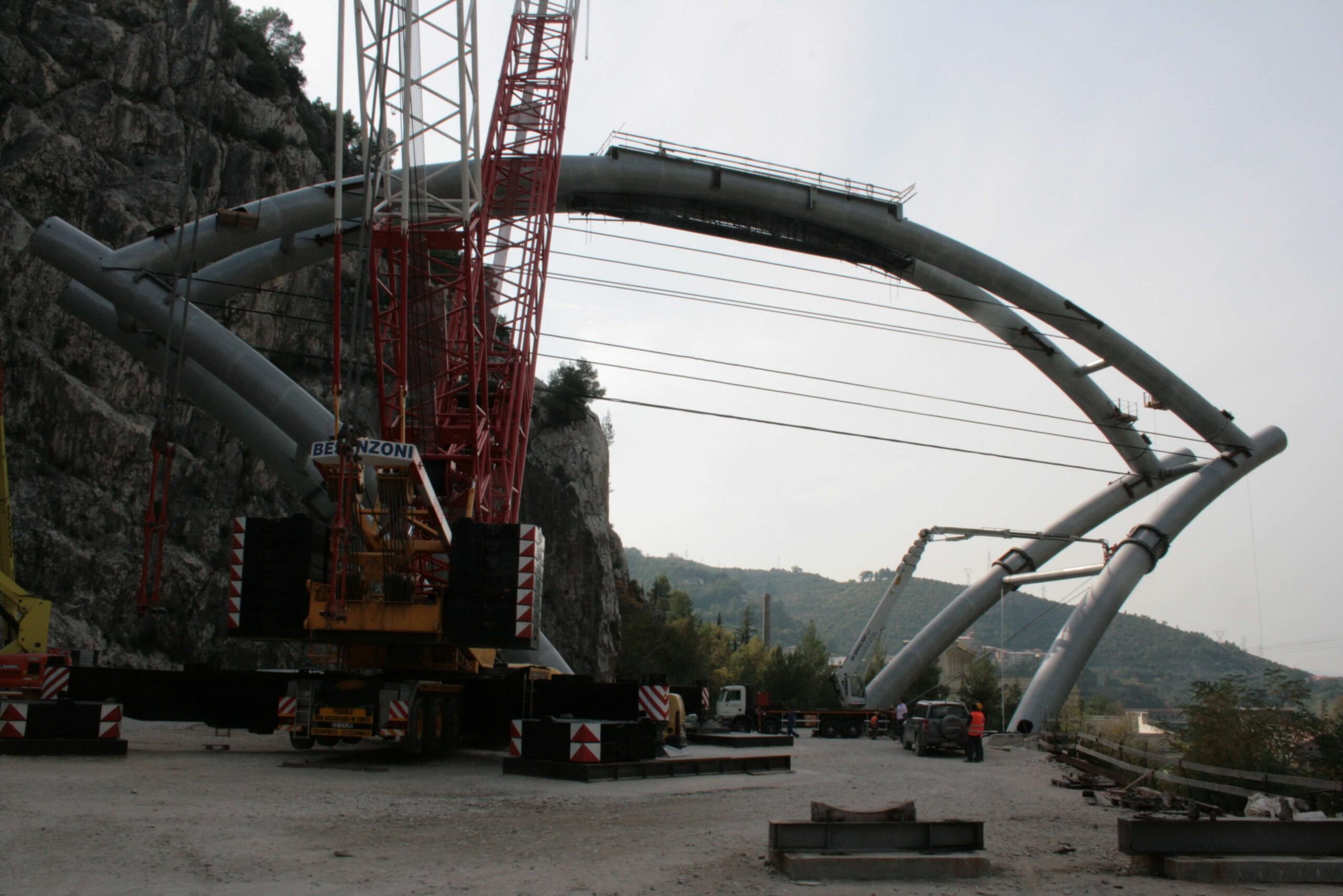
Assembly

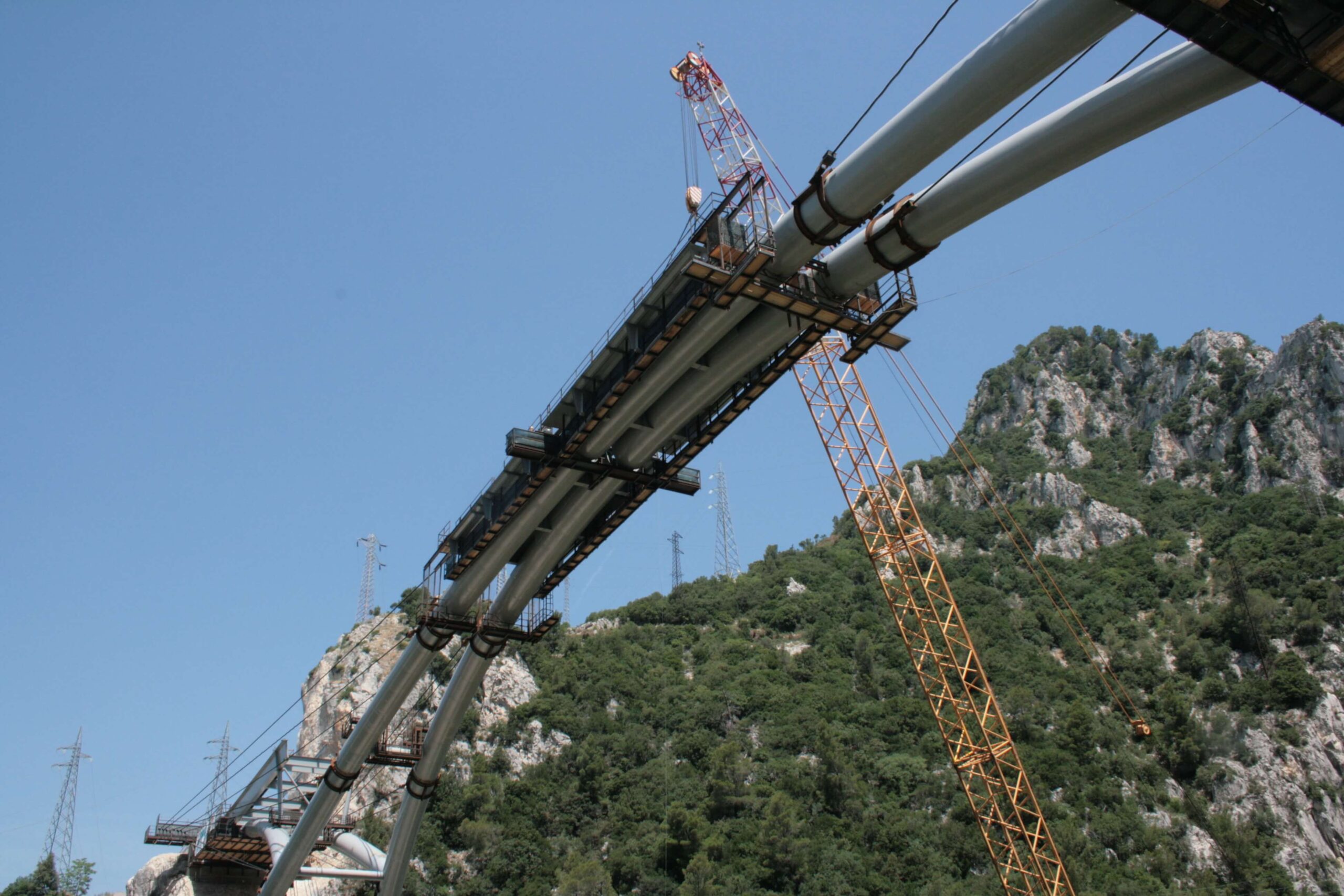
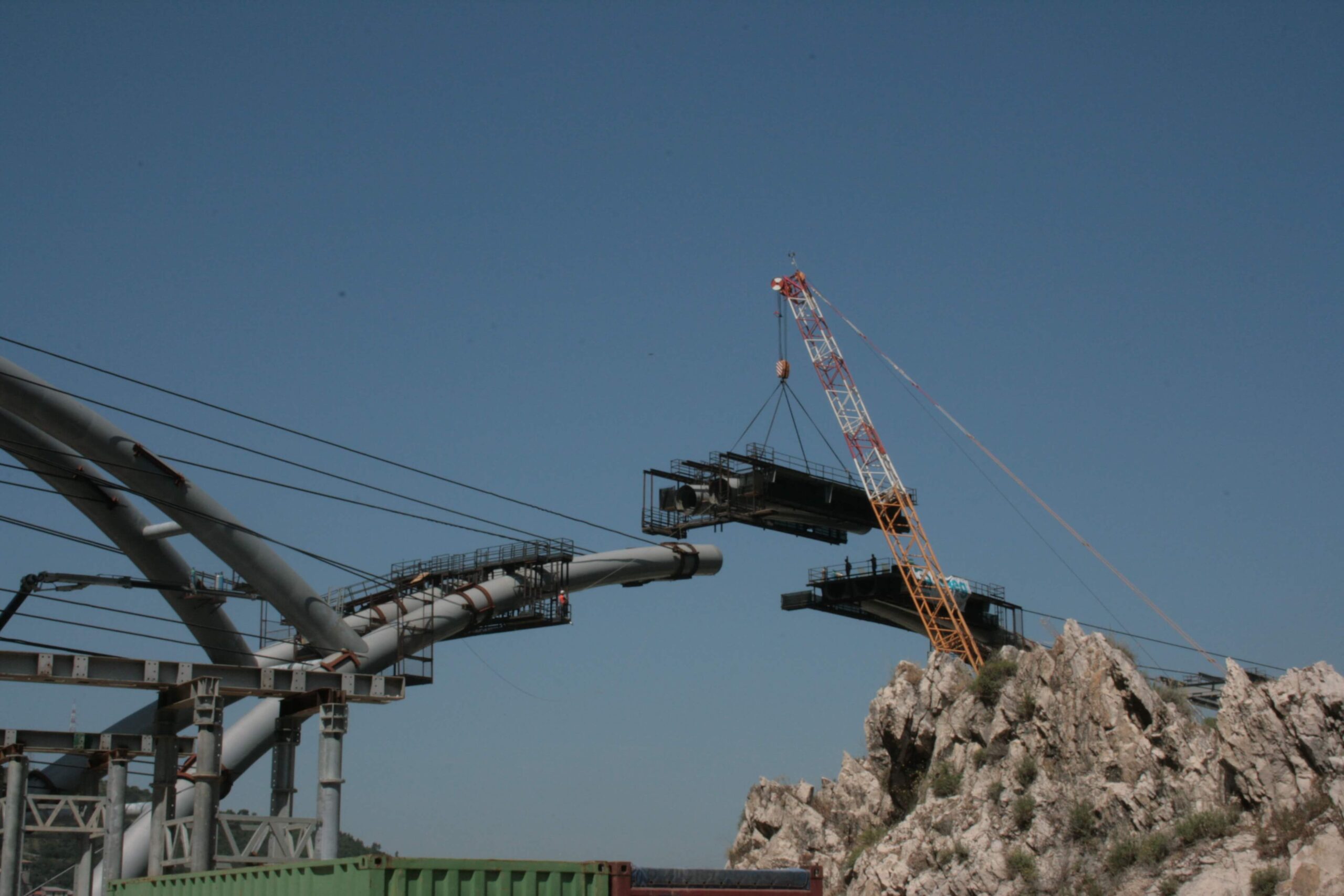
Assembly
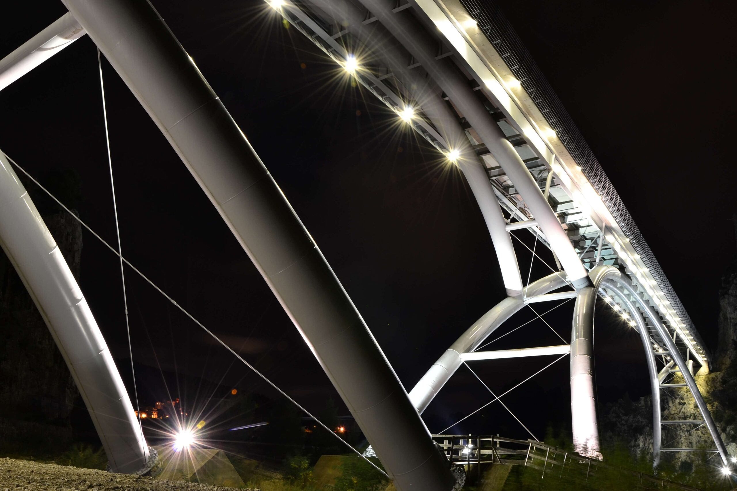
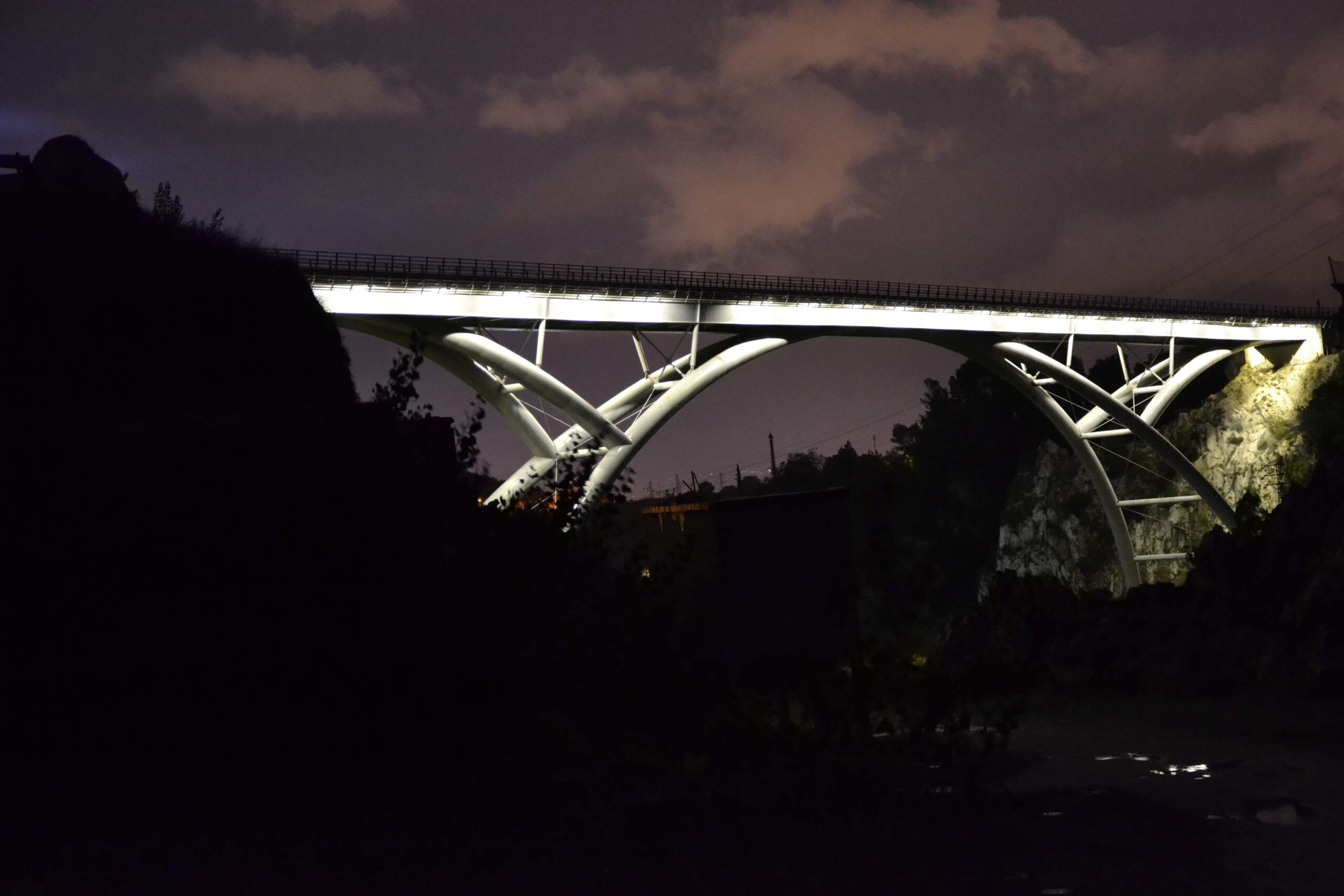
The orographical setting and the unique static layout with sequences of arches reminiscent of the pont des arts in Paris influenced the construction of the structure. Research into the assembly was carried out by Eng. Giorgio Rizzo. Construction was carried out in advance head on to the main arch using restraining stays connected both to the rocky slopes and self-anchored to the secondary frame arches to contain the thrust.